AFDEX
A Relief Pocket in the Die Reduces Punch Wear - About 23% Higher Without It
Tool wear is one of the key cost factors in hot forming. However, it can be influenced not only by tool material, coating or lubrication: In the case investigated, local punch wear was around 23% higher without a targeted modification of the die geometry. An optimized relief pocket in the die provides additional space for material displacement and thereby significantly reduces the load on the opposing punch – without increasing wear on the die.
MORPHOTEC used AFDEX to investigate how a targeted geometrical modification of the die affects wear in a particularly highly loaded region of the punch.
Three Forming Stages – Focus on the Third Stage
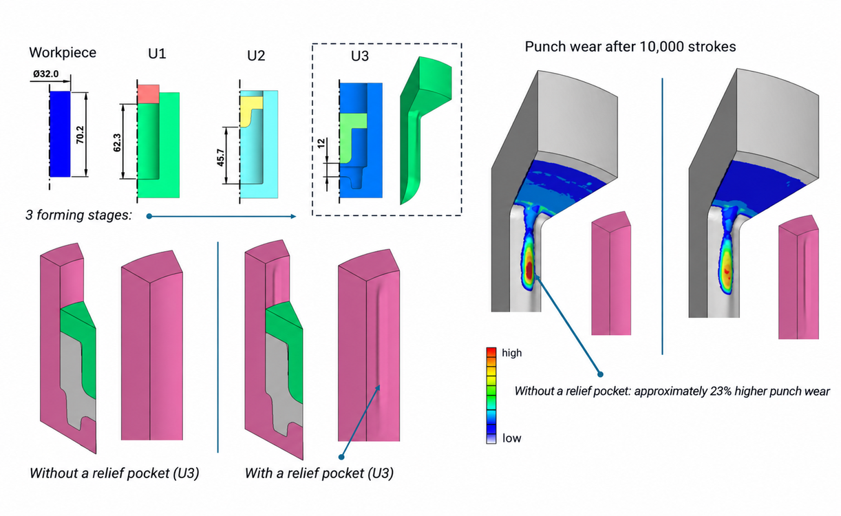
The investigated hot-forming process consists of three consecutive forming stages U1, U2 and U3. The wear investigation focused specifically on the third forming stage, as this is where the highly loaded punch region relevant to the investigation occurs.
The analysis was based on a three-dimensional 30° sector model with 12-fold cyclic symmetry. A rib-shaped tool protrusion on the punch forms a corresponding groove in the workpiece and thereby produces a pronounced three-dimensional material flow.
Two variants were compared in the third forming stage: the initial die geometry without a relief pocket and an optimized die with specifically created additional space for material displacement. The punch itself remained unchanged in both variants.
AISI 1020 was used as the workpiece material with an initial temperature of 1200 °C. The punch and die were made of the hot-work tool steel SKD61/H13. The initial tool temperature was 200 °C. The tools were modeled elastically. Heat transfer between the workpiece and the tools was also taken into account. The AFDEX standard setting for normal lubrication was used for the contact between workpiece and tool.
Temperature-Dependent Tool Wear
The wear model used, calibrated using experimental data, is based on an Archard-like approach. It takes into account tangential contact loading, the relative sliding motion between workpiece and tool, and the temperature-dependent hardness of the SKD61 tool material.
During the third forming stage, the local tool temperature in the highly loaded region reached around 400 °C and was therefore close to the upper temperature limit of the temperature-dependent wear model used.
Since the thermal conditions of the two investigated variants were virtually identical, the difference in calculated wear can essentially be attributed to the modified contact and material-flow conditions.
Around 23% Higher Punch Wear Without a Relief Pocket
Without a relief pocket, the maximum local punch wear after 10,000 strokes was 0.268 mm.
With the optimized relief pocket in the die, the corresponding value was 0.217 mm.
Relative to the optimized variant, local punch wear without the relief pocket was therefore around 23% higher.
The relief pocket becomes particularly effective during the second half of the forming stroke and in the decisive final phase. In this region, it provides the material with additional space for local displacement. Within the actually effective region, the available displacement volume is approximately equal to the volume of the corresponding active section of the rib-shaped tool protrusion during this forming phase.
This allows the material to redistribute more favorably. Tangential contact loading and relative sliding motion in the particularly wear-critical region of the punch are modified, significantly reducing the wear generated there.
At the same time, wear on the die did not increase.
Tool Geometry as an Additional Design Parameter
The result shows that reducing tool wear cannot be achieved exclusively through tool material, heat treatment, coating or lubrication. Specifically designed relief spaces in the die can also help reduce the loading of particularly highly stressed tool regions.
The around 23% higher local punch wear without the relief pocket demonstrates the economic potential of such geometrical optimization. Particularly in high-volume production, reduced tool wear, longer replacement intervals, and reduced downtime and rework can have a positive effect on production costs.
Assuming an approximately linear wear progression, the wear level reached after 10,000 strokes without a relief pocket would only be reached after around 12,300 strokes with the optimized relief pocket. This corresponds to approximately 2,300 additional strokes before reaching the same wear limit.
The investigation therefore demonstrates another approach to tool optimization: Not only the geometry of the highly loaded tool itself, but also the targeted design of the die can significantly influence local wear.
Approximately 23% higher punch wear without a relief pocket in forming stage U3 (© MORPHOTEC)
1 mm Larger Forming Tool Radius – 12% Lower Local Forming Damage
How strongly can a single forming tool radius influence local damage in a hot-formed component? MORPHOTEC investigated this question using AFDEX V24R02 on a two-stage hot forming process. Under constant process conditions, only the transition radius R2 was varied from 0.5 to 1.0 and 1.5 mm. The local Normalized Cockcroft-Latham damage value in the investigated region decreased from 0.33 to 0.29 – a reduction of 12%.
A functioning process does not necessarily mean that the tool geometry is optimal
When designing forming processes, the primary focus is initially on die filling, forming force, tool loading and the fundamental manufacturability of the component. These parameters are essential for process development. However, they do not fully describe the local material condition generated in the component by the forming process.
In practice, transition radii are often defined at an early stage of tool design. If the process subsequently appears uncritical in terms of die filling and forming force, there is initially little reason to question these radii again.
The AFDEX investigation shows, however, that a seemingly trouble-free process can conceal significantly different local damage states.
If such effects are only identified during physical trials, tool reworking or later component operation, modifications are considerably more costly than during simulation. Tools that have already been manufactured may have to be modified or replaced, test series repeated and, in the worst case, components that have already been produced reassessed.
The purpose of simulation is therefore not to make a functioning forming process more complicated, but to identify critical tool details before they result in costly tool corrections, scrap or avoidable component problems.
One radius is changed – the rest of the process remains unchanged
A two-stage axisymmetric AFDEX reference process served as the methodological starting point. Based on this process, an adapted MORPHOTEC tool geometry was developed for the investigation.
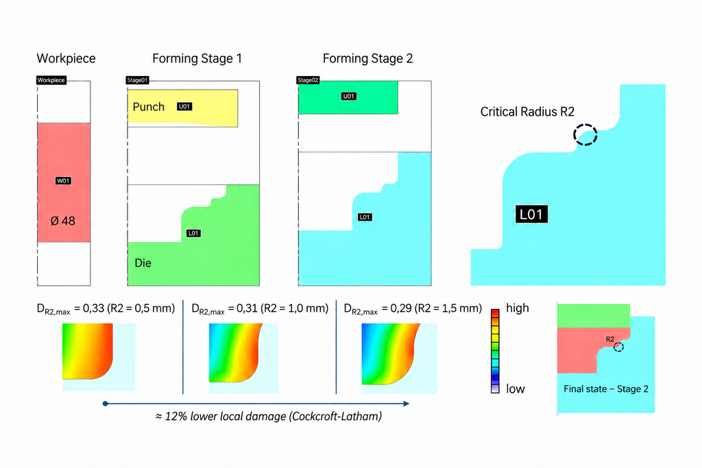
The process uses a cylindrical billet of approximately Ø48 × 54 mm made of AISI 1020 at an initial temperature of 1200 °C. After preforming in the first stage, the contour is further formed in the second forming stage.
The investigation focuses on the transition radius R2 in a region of pronounced material redirection.
The preceding radius R1 was kept constant at 6 mm for all variants. Only R2 was varied:
R2 = 0.5 mm, 1.0 mm and 1.5 mm.
Material, process parameters and the remaining geometry were unchanged between the comparative simulations. The region around transition radius R2 was resolved with sufficient mesh refinement for the local damage evaluation.
This makes it possible to investigate the influence of R2 specifically, without superimposing it with other geometric modifications.
Forming force does not reveal the local difference
The local effect of the radius cannot be identified from the global forming force.
The variants can appear almost identical in terms of overall process behaviour, while different local material states develop at the critical transition.
A force-displacement curve describes the global response of the forming process. However, it does not show the damage accumulated during the forming process in a specific local material region.
This is where an additional damage analysis provides information that cannot be obtained from forming force and die filling alone.
Cockcroft-Latham as a measure of local damage accumulation
For the evaluation, the Normalized Cockcroft-Latham damage parameter available in AFDEX was used.
The normalized Cockcroft-Latham criterion evaluates ductile damage accumulated during plastic deformation while taking the local stress state into account. The maximum principal normal stress is normalized by the von Mises equivalent stress and integrated over the equivalent plastic strain. Temperature and strain rate are not explicit components of the Cockcroft-Latham equation itself; their influence is taken into account through the temperature- and strain-rate-dependent material or flow-stress model used in the forming simulation.
Since no experimentally determined critical limit value for the material under investigation is used in this study, the calculated value serves for the direct comparison of the three geometric variants under identical process conditions.
The study therefore evaluates damage accumulation comparatively under identical thermal and process conditions; absolute fracture prediction is not the objective of this investigation.
Influence of R2 on local damage
For a geometrically identical evaluation region at transition radius R2, the following local maximum values were obtained:
R2 = 0.5 mm: local maximum value 0.33
R2 = 1.0 mm: local maximum value 0.31
R2 = 1.5 mm: local maximum value 0.29
Increasing R2 from 0.5 to 1.5 mm reduces the local Cockcroft-Latham value by 12%.
At least as informative as the maximum values is the spatial distribution of the damage.
All three variants were displayed using an identical contour scale. This makes it immediately apparent that increasing the radius not only reduces the local peak value. At the same time, the spatial extent of the red and orange regions representing higher damage also decreases.
The difference is therefore not limited to a single numerical peak value. The local damage zone in the investigated transition region also becomes smaller.
High local plastic deformation at the transition radius
In the region of R2, the equivalent plastic strain is approximately 70%. The investigated transition therefore belongs to the locally highly plastically deformed regions of the component.
Particularly in regions of high plastic deformation combined with pronounced material redirection, the design of a tool transition can have a relevant influence on the local material condition.
However, the investigation does not imply that increasing a tool radius by 1 mm will result in 12% lower damage in every forming process.
The magnitude of the effect depends on geometry, material, process conditions, material flow and local loading. At a less severely deformed location, the same change in radius may have a considerably smaller influence.
The benefit of simulation lies in identifying and evaluating such sensitive tool regions for the specific forming process.
Not every region of local forming damage is equally critical for the component
An increased Cockcroft-Latham value does not automatically mean that the finished component will later fail at this location.
For the technical assessment, the decisive factor is where the pre-damage generated by the forming process is located in the finished component and what mechanical loading this region will experience during operation.
If increased forming damage occurs in a region that is subsequently removed by machining or is subjected to only low mechanical loading, its significance may be limited.
The situation is different when increased pre-damage from the forming process and high mechanical loading during subsequent operation occur in the same component region. In this case, the manufacturing history may become relevant to fracture initiation and fatigue life.
A 12% reduction in the Cockcroft-Latham damage parameter cannot be translated into a corresponding percentage increase in service life. A quantitative fatigue-life assessment would additionally require the actual operating loads, a fatigue analysis and, where appropriate, experimental investigations.
How many additional load cycles can ultimately be achieved depends on the specific operating loading and cannot be determined from the Cockcroft-Latham value alone.
For further validation, the critical damage value for a specific material and process can be calibrated experimentally. For example, local fracture can deliberately be induced by increasing the severity of a critical tool radius, and the corresponding forming test can then be reproduced in AFDEX. The Cockcroft-Latham value calculated at the location of fracture initiation can subsequently serve as a reference for evaluating further tool variants.
The forming simulation thus provides an important piece of initial information: It shows the local material condition in which the component leaves the manufacturing process.
Die filling and forming force alone are not always sufficient
The investigation highlights an aspect of tool design that may remain hidden if only conventional process parameters are considered.
A forming process can appear uncritical in terms of die filling and global process behaviour while still generating different local damage states within the material.
In the investigated example, changing transition radius R2 from 0.5 to 1.5 mm under otherwise identical boundary conditions resulted in 12% lower local damage accumulation. At the same time, with an identical contour scale, the zone of increased damage became visibly smaller.
For simulation-based tool development, this means that in addition to die filling and forming force, local damage indicators can provide important additional information.
The question therefore expands from
“Can the component be manufactured with this tool?”
to
“What local material condition does the forming process generate in the finished component?”
Particularly for components in which highly formed regions are subsequently subjected to high mechanical loads, this additional consideration can be relevant to tool and process design.
It can also help to evaluate tool details before manufacturing, rather than identifying weak points only during physical trials and subsequently having to modify or replace tools.
Reducing Material Use in Bulk Metal Forming - Billet and Process Optimization with AFDEX
Material costs have a direct impact on the economic efficiency of components produced by bulk metal forming. At the same time, the amount of starting material cannot simply be reduced without limit. If too little material is provided or if it is distributed unfavorably, areas of the die cavity may not be completely filled, required machining allowances may be insufficient, or the process may become unstable. The key question is therefore not simply how to use as little material as possible, but rather: How far can the billet be reduced without compromising reliable production of the component?
MORPHOTEC uses AFDEX to determine this limit before physical die tryout and to systematically coordinate die geometry, billet design, and process parameters. As an AFDEX partner with a sales territory covering the European Union, Switzerland, Liechtenstein, and the United Kingdom, MORPHOTEC works closely with MFRC, the developer of AFDEX. Through this close cooperation with MFRC, direct exchange with AFDEX developers and researchers, and the involvement of specialists and research partners from the AFDEX environment, MORPHOTEC has extensive methodological and process expertise that is directly applied in industrial customer projects.
Less Material Is Only Better if the Process Still Works
In industrial practice, the required amount of starting material is often specified with a certain material allowance. This allowance increases process robustness but also adds material cost. Simply reducing billet size based on experience, empirical rules, or trial and error is therefore not a state-of-the-art optimization approach. What matters is how changes in material volume and die geometry affect material flow throughout the entire forming process.
AFDEX makes it possible to investigate these relationships virtually. Different geometries and material volumes can be simulated and compared with respect to die filling, material flow, forming force, and other relevant process variables. A general safety allowance can therefore be transformed into a technical optimization problem with clearly defined constraints.
MORPHOTEC uses this approach for simulation-based optimization of material utilization and forming processes. A published project from the AFDEX development and research environment demonstrates the method using a high-strength ball nut for the gear actuator of a dual-clutch transmission. For this geometrically demanding component, a closed-die cold forming process was investigated and optimized with AFDEX. The original manufacturing route was based on casting, while the subsequent investigations aimed, among other objectives, at improving productivity, reducing manufacturing costs, and lowering material consumption.
Die Geometry Determines the Required Material Volume
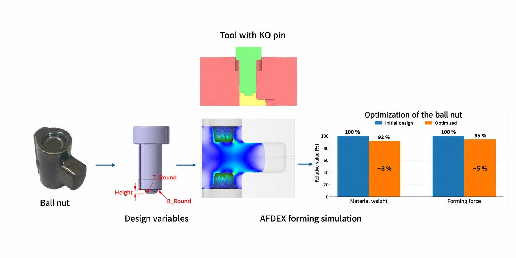
A particularly interesting aspect of this example is that the optimization did not simply involve changing the diameter or length of the billet. Instead, the researchers specifically investigated the geometry of the KO pin, or knock-out pin, which significantly influences material distribution in an important region of the component during closed-die cold forming.
Three geometric parameters were selected as design variables:
the height of the KO-pin projection: 4, 6, or 8 mm,
the upper radius of the projection: 1, 2, or 3 mm, and
the lower radius of the projection: 1, 2, or 3 mm.
The three parameters were investigated in nine selected design combinations using a Taguchi/DOE approach and AFDEX simulations. Instead of physically manufacturing and testing numerous die variants one after another, the influence of the individual geometric parameters could therefore be evaluated systematically.
Material Savings Under a Clearly Defined Technical Constraint
The optimization target was the volume of material required for manufacturing the component. At the same time, reducing the material volume could not be allowed to result in insufficient filling of regions required for subsequent machining.
For this purpose, the project evaluated the length of a material region reserved for subsequent machining. A minimum length of 23 mm had to be maintained. The simulation therefore had a clearly defined task: minimize the required material volume while simultaneously ensuring that the minimum geometry necessary for manufacturing remained available.
This constraint is crucial for industrial application. An optimization that merely produces a mathematical minimum for billet volume would be of little value if the component could no longer be manufactured and machined reliably, or if the required dimensional and geometric tolerances could no longer be achieved. AFDEX, by contrast, allows material usage and process requirements to be considered together.
Three Die Parameters - Nine Variants - One Targeted Solution
The AFDEX evaluations showed that all three investigated KO-pin parameters had a significant influence on the required material volume. The lowest required volume was predicted for the following parameter combination:
projection height: 8 mm
upper radius: 1 mm
lower radius: 3 mm
This demonstrates a key advantage of simulation-based process development: it does not merely identify a better result. It also makes it possible to understand which specific geometric change influences that result and in which direction the corresponding design parameter needs to be adjusted.
The methodology used in this reference project -- selecting technically adjustable design variables, generating targeted design variants, performing AFDEX simulations, and subsequently optimizing the process under defined constraints -- corresponds to the type of simulation-based process development that MORPHOTEC applies to industrial forming applications using AFDEX.
Eight Percent Less Material - and Lower Forming Force at the Same Time
The AFDEX Newsletter Q1/2020 provides a quantitative summary of the three-dimensional optimization of the closed-die cold forming process for the ball nut. Compared with the initial design, the material weight was reduced by 8 percent. At the same time, the required forming force decreased by 5 percent.
The result is significant in two respects. Reducing material weight directly lowers the amount of raw material required per component. At the same time, the optimized design in this case also reduced the required forming force by 5 percent. A lower forming force also reduces the mechanical load on the press and may decrease the energy required for the forming operation. At high production volumes, this can result in relevant energy savings during production.
The optimization therefore goes far beyond simply shortening a billet: die geometry, material flow, required material volume, and forming force are treated as an interconnected system.
Virtual Variants Instead of Die Corrections After Tryout
Especially in complex bulk metal forming processes, even small geometric changes can have a major influence on material flow. Determining which combination of die geometry and material volume provides the best compromise therefore cannot always be predicted reliably from experience alone.
Experience remains indispensable in process development. Simulation, however, allows this experience to be extended systematically: variants can be investigated virtually, unsuitable solutions can be eliminated, and promising geometries can be identified before dies are modified or new billet dimensions are tested in production.
This effect was explicitly highlighted in the ball-nut project. By combining systematic design variation with AFDEX simulation, the process optimization could be carried out in a structured manner while reducing the development effort required.
Material Efficiency Begins with Process Design
For manufacturing companies, reducing raw-material consumption results in a direct economic benefit that multiplies accordingly at high production volumes. The decisive factor is that this material reduction must be technically validated and must not come at the expense of die filling, machining allowances, or process robustness.
AFDEX can, for example, be used to investigate systematically:
how far billet volume can be reduced,
which die parameters determine material requirements,
whether all critical regions continue to be completely filled,
which machining allowances must be maintained,
how different variants affect material flow and forming force, and
which combination of billet and die geometry produces the most favorable process.
Material efficiency can therefore be integrated directly into process development instead of removing excess material after forming through trimming or machining.
The close relationship between MORPHOTEC and the AFDEX development environment is an important part of this service offering. MORPHOTEC combines its own long-standing experience in numerical simulation and industrial process development with the methodological and process expertise of the AFDEX developers. Challenging tasks are not treated merely as isolated software applications but are addressed in greater technical depth through the involvement of AFDEX developers, researchers, and other specialists from the AFDEX environment.
AFDEX as an Engineering Service or for In-House Simulation
MORPHOTEC provides forming simulation with AFDEX as an engineering service and distributes the AFDEX software throughout the European Union, Switzerland, Liechtenstein, and the United Kingdom. Companies can have MORPHOTEC investigate and optimize tasks such as reducing material consumption, optimizing billet and die geometries, solving material-flow problems, or determining forming forces.
Alternatively, following appropriate training, AFDEX can be used for in-house simulation. MORPHOTEC supports customers in getting started with the software and applying it across a broad range of metal forming processes -- from cold and hot forming to extrusion, drawing, and rolling, as well as selected sheet metal forming applications.
Customers therefore gain more than access to simulation software alone. They benefit from the combination of MORPHOTEC's industrial CAE experience, direct cooperation with AFDEX developer MFRC, and the expertise of researchers and other partners within the AFDEX environment.
References
Lee, Y. H.; Park, M. C.; Kim, M. C.; Joun, M. S.; Kim, B. M.; Kim, D. H. (2019):
Development of Cold Forming Process for Productivity Improvement of Actuator Ball Nut with Complex Shape and High Strength.
Korean Society for Technology of Plasticity, Fall Conference 2019, pp. 194-195.
MFRC (2020):
AFDEX Newsletter Q1/2020 - Successful Application Cases of AFDEX, Optimal Design for 3D Die Shape.
Detecting and Minimizing Underfill in Bulk Metal Forming at an Early Stage - Process Optimization with AFDEX
Underfill is one of the typical quality problems in bulk metal forming and can have immediate economic consequences. If a region of the die cavity is not completely filled during the forming process, the result may be scrap, rework, die corrections and additional tryout loops. Especially for complex forged parts, it is therefore not sufficient to consider only the final geometry. What matters is how the material is distributed throughout the individual forming stages, which flow paths develop, and whether the material reaches critical regions of the die cavity in time and in sufficient quantity.
MORPHOTEC uses AFDEX to analyze such relationships predominantly in 3D before physical die tryout and to systematically optimize forming processes. As an AFDEX partner with a sales territory covering the European Union, Switzerland, Liechtenstein and the United Kingdom, MORPHOTEC works closely with MFRC, the developer of the AFDEX software. Through its close cooperation with MFRC, direct technical exchange with AFDEX developers and researchers, and the involvement of specialists and research partners from the AFDEX environment in demanding projects, MORPHOTEC has extensive methodological and process expertise that is directly applied in industrial customer projects. MFRC develops AFDEX on the basis of extensive research in bulk metal forming and cooperates internationally with industrial and research partners.
Underfill is often a material-flow problem
Insufficient material volume is only one possible cause of underfill. Even when the available billet volume is fundamentally sufficient, die filling may still be inadequate. Possible causes include an unsuitable preform, unfavorable volume distribution, long or competing material-flow paths, or a die geometry that prevents sufficient material from reaching certain areas.
This is precisely where forming simulation provides a decisive advantage: material flow is not evaluated only at the finished component but is tracked throughout the entire process. Areas with insufficient die filling can be localized, while at the same time the effects of changes to the preform or process sequence on material distribution can be investigated.
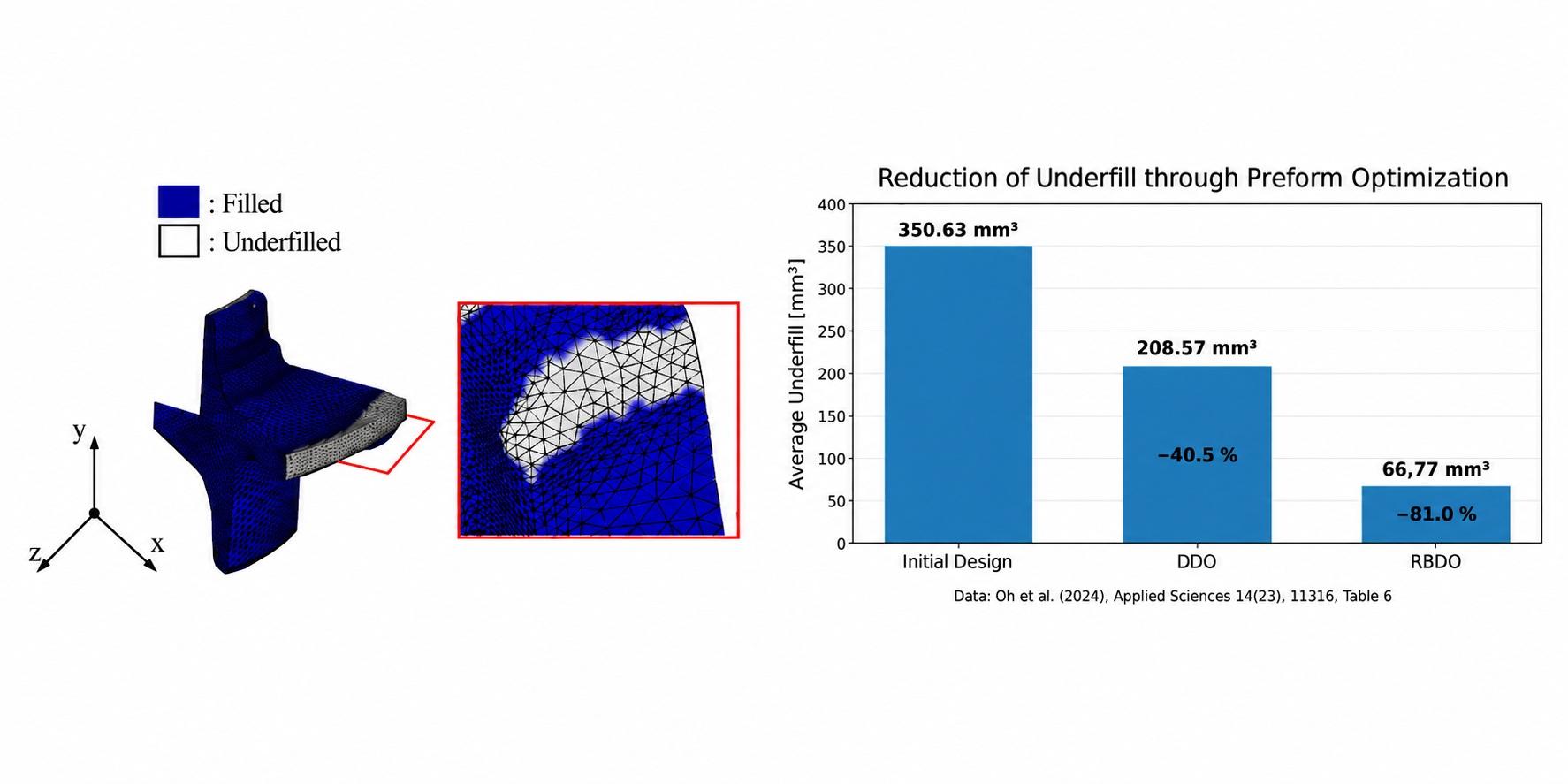
MORPHOTEC uses this approach for the simulation-based analysis and optimization of forming processes. A published bearing-hub project from the AFDEX development and research environment demonstrates how powerful this approach can be, particularly for preform optimization. In this project, the preform of a hot-forged bearing hub was systematically varied with AFDEX 24R01 and optimized with respect to underfill.
Six geometric parameters define the preform
The bearing hub is manufactured in several forming stages. The investigated process chain consists of three stages and was simulated using a three-dimensional 36? sector model, corresponding to one tenth of the complete component. AISI 1055 was used as the workpiece material. The FE model started with approximately 20,000 elements and was increased to as many as 60,000 elements during the calculation.
However, the optimization was not based solely on a detailed simulation of the existing process. The preform geometry was systematically parameterized. Six variables were varied:
- an angle in the lower outer region,
- the lower inner diameter,
- the upper and lower height,
- the depth in the central region, and
- a radius in the lower inner region.
These parameters directly determine where material is already located within the preform and which flow paths it must follow during the subsequent finish-forging operation. They therefore modify precisely those geometric factors that are decisive for sufficient die filling. The authors selected these parameters because of their influence on defect formation, material and volume distribution, forming quality and overall formability.
For an initial assessment, the six geometric parameters were investigated in 64 different combinations using a full factorial experimental design. The subsequent sensitivity analysis showed that the lower height of the preform in particular has a strong influence on underfill and forming force. The simulation therefore does not merely establish that a defect exists - it reveals which geometric parameter has a major influence on the defect.
From defect detection to targeted optimization
This is precisely where systematic simulation-based process development differs from the mere visualization of results. A critical region is not simply highlighted in the simulation. The geometric parameters are varied, their effects on material flow and die filling are calculated, and an improved preform is derived from the results.
For the subsequent optimization, the six geometric design variables were supplemented by three additional variables to account for manufacturing tolerances. Based on the resulting nine variables, 300 data points were generated using an Optimal Latin Hypercube Design. Various surrogate models were built and compared on this data basis; the Kriging model was selected for the subsequent optimization. It was then used as the basis for both deterministic optimization and reliability-based optimization - Reliability-Based Design Optimization, RBDO. In the latter approach, manufacturing tolerances and variations are explicitly included in the optimization. The optimized process is therefore intended not only to function under idealized nominal conditions but also to remain robust against real manufacturing variations.
The approach used in this reference project - parameterization of the preform, sensitivity analysis and subsequent optimization - corresponds to the type of simulation-based process development that MORPHOTEC uses with AFDEX for industrial applications.
The results are significant: in the initial design, the mean underfill volume was 350.63 mm3. Deterministic optimization reduced this value to 208.57 mm3. With reliability-based optimization, it was reduced further to 66.77 mm3.
An even more informative indicator is process reliability. The calculated probability of violating the defined underfill criterion was 69.59 percent for the initial design. After deterministic optimization, it was reduced to 18.01 percent. For the robustly optimized RBDO design, it fell to only 0.81 percent.
This demonstrates the key economic benefit of simulation: a previously observed die-filling problem is translated into specific geometric design variables, these variables are optimized virtually, and their effects are evaluated quantitatively.
Process expertise instead of trial and error
For industrial forging companies, this approach means that preform development does not have to rely exclusively on experience followed by physical die tryout. Experience remains indispensable, but it can be complemented by a systematic analysis of material flow performed predominantly in 3D.
AFDEX makes it possible to compare different preforms and process variants before modifying the die. This allows the causes of underfill to be narrowed down more systematically and promising variants to be identified before they are implemented in steel. This does not automatically eliminate every physical trial, but it can significantly reduce the number of costly correction loops and make process development considerably more targeted.
The close connection between MORPHOTEC and the AFDEX development environment is an essential part of the service offering. MORPHOTEC combines its own long-standing experience in numerical simulation and industrial process development with the methodological and process expertise of the AFDEX developers. Demanding tasks are therefore not treated as isolated software applications but are addressed in greater technical depth through the involvement of AFDEX developers, researchers and other specialists from the AFDEX environment.
AFDEX as an engineering service or for in-house simulation
MORPHOTEC provides forming simulations with AFDEX as an engineering service and distributes the AFDEX software throughout the European Union, Switzerland, Liechtenstein and the United Kingdom. Companies can have specific issues such as underfill, insufficient die filling, critical material flow or preform design analyzed and optimized by MORPHOTEC.
Alternatively, AFDEX can be used for a company's own in-house simulation activities following appropriate training. MORPHOTEC supports customers in getting started with the software and applying it across a broad range of metal-forming processes - from cold and hot forming to extrusion, drawing and rolling, as well as selected sheet-metal-forming applications.
Customers therefore gain more than access to simulation software. They benefit from the combination of MORPHOTEC's industrial CAE experience, direct cooperation with MFRC, the developer of AFDEX, and the expertise of researchers and other partners from the AFDEX environment. MFRC itself identifies international cooperation and collaborative research as integral elements of its AFDEX development strategy.
Reference
Oh, M.; Kim, J.; Cho, J.; Kim, M.; Joun, M.; Hong, S. (2024):
Reliability-Based Design Optimization of Bearing Hub Preform for Minimizing Defects Considering Manufacturing Tolerance in Hot Forging Process.
Applied Sciences, 14(23), 11316. DOI: 10.3390/app142311316.
Optimizing Tool Life in Metal Forming - Fatigue Life Analysis with AFDEX
Premature tool failure and insufficient tool life are among the major cost and production risks in highly loaded metal forming processes. Modern forming simulation makes it possible not only to investigate material flow in the workpiece, but also to analyze the resulting tool loads and fatigue life. MORPHOTEC uses the metal forming simulation software AFDEX for this purpose.
In cold forming processes, tools are primarily subjected to high mechanical cyclic loads. In hot forming processes, significant thermomechanical cyclic loads occur in addition. Critical regions often develop locally at transitions, radii, tool edges or highly loaded inserts. A tool may therefore fail even though the overall tool loading initially appears uncritical.
Improving tool life therefore requires more than simply considering the maximum forming force or a single equivalent stress value. Of particular importance is how the loading develops throughout the forming cycle and which stress state is already present in the tool before the actual forming operation begins.
HCF and LCF - Different Regimes of Tool Fatigue
Fatigue is generally divided into High-Cycle Fatigue (HCF) and Low-Cycle Fatigue (LCF). In the HCF regime, cyclic material loading remains essentially elastic and is designed for a high number of load cycles. In the LCF regime, by contrast, significant cyclic plastic strains occur. Local regions of the material are subjected to plastic deformation. This may be permissible in tool design provided that the required tool life or specified number of load cycles is reliably achieved.
For cold forming tools used in high-volume production, HCF life is of particular importance. In hot forming tools, LCF may also play a major role in tool life because of the thermomechanical cyclic loading involved.
The stress state of a cold forming tool differs significantly from that of many conventional structural components. Tool inserts made of carbide or tool steel are frequently prestressed by means of stress rings. The interference fit, shrink fit or press fit deliberately introduces compressive stresses into the tool insert. The surrounding stress ring correspondingly carries tensile stresses.
This compressive prestress is intended to counteract tensile stresses generated during the forming operation. The stresses resulting from the forming process are superimposed on the existing prestress state. Joun et al. show that prestressed inserts exhibit initial mean stresses in the compressive range; during forming, these stresses may change and, at critical locations, may even shift into the tensile range.
This illustrates why the design of the prestress condition can have a major influence on tool life.
A Fatigue Model Specifically Adapted to Cold Forming Tools
The complexity of predicting the fatigue life of prestressed cold forming tools is demonstrated in a 2022 study published in Materials by Joun et al. The work originates from the AFDEX development group and is listed by AFDEX among research activities contributing to the development of new or improved AFDEX functionality.
The study starts from a fundamental problem: classical fatigue models were primarily developed for the design of structural components. In such applications, conservative design is often the main objective. The stress states occurring in highly prestressed cold forming tools, however, differ substantially from those in conventional structural components.
One widely used approach is the Goodman-Haigh diagram, which describes the relationship between mean stress and permissible stress amplitude using a linear relationship. The approach is intentionally conservative. The well-known Gerber model, by contrast, uses a curved relationship and may represent experimental fatigue data more accurately in some cases. According to Joun et al., however, neither the classical Goodman-Haigh model nor the Gerber model is optimal over the entire stress range relevant to highly loaded tool materials such as WC-Co.
Joun et al. therefore developed a generalized fatigue limit diagram combining elements of both approaches. A material-dependent exponent allows the curve to be adjusted between a Goodman-Haigh-type linear relationship and a Gerber-type nonlinear relationship. At the same time, the model takes the yield limits of the tool material into account and extends the description specifically into the range of mean stresses in the compressive range, which is particularly important for prestressed tools.
This stress range is highly relevant for cold forming tools: because compressive prestress is deliberately introduced, the tool insert does not start from a mean stress of zero, but already from a compressive mean-stress state. Fatigue strength therefore cannot be evaluated adequately if this range is treated only by means of a simplified standard assumption. Experimental data for WC-Co20% used in the study also showed a significant influence of compressive mean stresses on equivalent fatigue strength.
The model therefore combines mean stress, stress amplitude, material properties and experimental fatigue data in order to determine an equivalent fatigue loading for the actual stress state and to derive the corresponding HCF life.
Comparison with a Real Cold Forming Tool
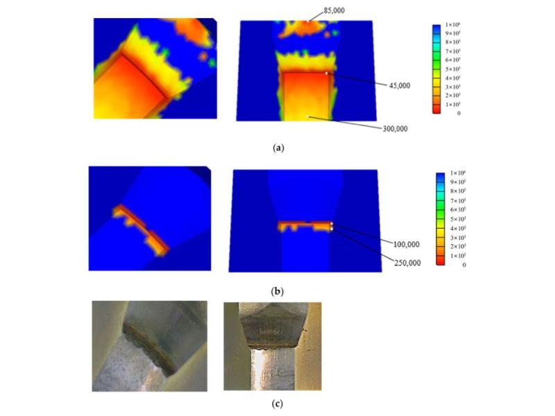
Among the cases investigated was a multi-stage cold forming process for an automotive nut made of S25C. The tool system contained prestressed WC-Co20% inserts and stress rings. The loading generated by the forming process was determined using an implicit finite element simulation and subsequently used for structural analysis and fatigue life evaluation of the tool.
For one critical tool insert, the modified Goodman-Haigh evaluation predicted a minimum HCF life of approximately 45,000 cycles, whereas the newly developed fatigue model predicted approximately 100,000 cycles.
Even more important than the numerical value itself was the spatial prediction. With the extended model, the calculated critical life region was concentrated much more strongly in the area where HCF failure was also observed in the real tool. The authors describe the agreement between simulation and experimental findings as qualitatively good.
The example demonstrates that the choice of fatigue model is not merely an academic issue. It can significantly influence both the predicted life and the localization of the truly critical tool region.
Tool, Billet and Forming Process Constitute One Interacting System
A further study published in 2024 by Byun et al. shows that the cause of tool failure does not necessarily lie solely in the tool geometry itself. The authors investigated the automatic multi-stage cold forging of an automotive wheel nut made of S25C.
Geometrical asymmetries created during shearing of the billet caused tilting and wobbling of the workpiece during the forming operation, shifting its center of mass and leading to asymmetric loading. This resulted in local stress concentrations in critical tool regions that were associated with the observed HCF failure.
AFDEX addresses precisely this interaction in its technical documentation: for short billets produced by shearing, such as those used for nuts, the geometry of the sheared surface can already have a significant influence on the local stress distribution in highly critical tool regions. AFDEX demonstrates both the shearing simulation itself and the resulting tool stress distribution.
This example highlights an important advantage of an integrated forming simulation: the cause of insufficient tool life may lie outside the tool region in which failure actually occurs. Billet geometry, material flow, process sequence, friction, tool prestress and elastic tool response can interact and, under unfavorable conditions, reinforce one another in terms of local tool loading.
From Failure Analysis to Tool Life Optimization
An appropriate AFDEX analysis can therefore be used to investigate a variety of factors, including critical tool stresses and their evolution over time, prestress and stress-ring design, tool radii and transition regions, loads generated in individual forming stages, and the influence of billet geometry and process conditions.
The objective is not merely to reproduce a tool failure that has already occurred. Simulation can be used during process and tool development to identify critical regions before tooling is manufactured and to compare different design variants virtually.
MORPHOTEC offers both forming simulation services using AFDEX and the distribution of the AFDEX software. Companies can initially have specific process or tooling problems investigated by MORPHOTEC, or they can use AFDEX for in-house simulation after appropriate training. MORPHOTEC supports customers in getting started with and applying the software across a broad range of metal forming processes - from cold and hot forming to extrusion, drawing and rolling, as well as selected sheet metal forming applications.
AFDEX is therefore suitable both for companies seeking to investigate a specific problem involving insufficient tool life and for manufacturers wishing to integrate simulation-based process and tool development permanently into their own engineering environment.
References
Joun, M. S.; Ji, S. M.; Chung, W. J.; Cho, G. S.; Lee, K. H. (2022):
A New General Fatigue Limit Diagram and Its Application of Predicting Die Fatigue Life during Cold Forging.
Materials, 15(7), 2351. DOI: 10.3390/ma15072351.
Byun, J. B.; Abd Hamid, N.; Cho, G. S.; Chung, W. J.; Kang, S. M.; Lee, K. H.; Joun, M. S. (2024):
Effect of shearing on production stability and die life in automatic multi-stage cold forging of an automobile wheel nut.
The International Journal of Advanced Manufacturing Technology, 131, 329-341. DOI: 10.1007/s00170-024-13017-9.
MORPHOTEC becomes a sales partner of MFRC (AFDEX) | AFDEX – Software for forming process simulation
At the beginning of 2024, MORPHOTEC became a sales partner of MFRC for the EU region and Switzerland. MFRC has been developing and distributing the CAE software AFDEX since 1995. AFDEX makes it possible to simulate highly complex forming processes.
Examples of forming simulations successfully performed with AFDEX include:
- Closed-die forging
- Fine blanking
- Coining
- The Mannesmann process
- Embossing
- Cold and hot forming
- Deep drawing
AFDEX has particular strengths in analyzing and displaying flow lines and grain flow during forming.
AFDEX also includes an extensive material database with temperature- and strain-rate-dependent flow curves. The database can be supplemented with data from users’ own material tests.
Intuitive preprocessing and postprocessing that can be learned quickly enable users to carry out their first analyses without a large time investment.
AFDEX currently uses rigid- or elastic-viscoplastic finite element simulation methods, with the option of incorporating both steady-state and transient temperature-field simulations.
The software system consists of modules that can be selected to suit the intended application.
The AFDEX 2D and AFDEX 2D/DIE modules use quadrilateral finite elements.
AFDEX 3D, AFDEX 3D/OPEN and AFDEX 3D/DIE use tetrahedral finite elements.
AFDEX 2D/DIE and AFDEX 3D/DIE are simulation modules for structural analysis of dies that can be used in conjunction with the corresponding AFDEX 2D and AFDEX 3D forming simulation systems. AFDEX MAT enables users to calibrate stress-strain curves from experimental data, among other functions.
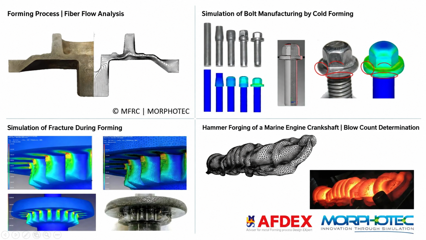
The image shows various examples of forming simulations, illustrating the broad range of applications available with AFDEX.
Further information is available at www.morphotec.de and www.afdex.com.