Optimizing Tool Life in Metal Forming - Fatigue Life Analysis with AFDEX
Premature tool failure and insufficient tool life are among the major cost and production risks in highly loaded metal forming processes. Modern forming simulation makes it possible not only to investigate material flow in the workpiece, but also to analyze the resulting tool loads and fatigue life. MORPHOTEC uses the metal forming simulation software AFDEX for this purpose.
In cold forming processes, tools are primarily subjected to high mechanical cyclic loads. In hot forming processes, significant thermomechanical cyclic loads occur in addition. Critical regions often develop locally at transitions, radii, tool edges or highly loaded inserts. A tool may therefore fail even though the overall tool loading initially appears uncritical.
Improving tool life therefore requires more than simply considering the maximum forming force or a single equivalent stress value. Of particular importance is how the loading develops throughout the forming cycle and which stress state is already present in the tool before the actual forming operation begins.
HCF and LCF - Different Regimes of Tool Fatigue
Fatigue is generally divided into High-Cycle Fatigue (HCF) and Low-Cycle Fatigue (LCF). In the HCF regime, cyclic material loading remains essentially elastic and is designed for a high number of load cycles. In the LCF regime, by contrast, significant cyclic plastic strains occur. Local regions of the material are subjected to plastic deformation. This may be permissible in tool design provided that the required tool life or specified number of load cycles is reliably achieved.
For cold forming tools used in high-volume production, HCF life is of particular importance. In hot forming tools, LCF may also play a major role in tool life because of the thermomechanical cyclic loading involved.
The stress state of a cold forming tool differs significantly from that of many conventional structural components. Tool inserts made of carbide or tool steel are frequently prestressed by means of stress rings. The interference fit, shrink fit or press fit deliberately introduces compressive stresses into the tool insert. The surrounding stress ring correspondingly carries tensile stresses.
This compressive prestress is intended to counteract tensile stresses generated during the forming operation. The stresses resulting from the forming process are superimposed on the existing prestress state. Joun et al. show that prestressed inserts exhibit initial mean stresses in the compressive range; during forming, these stresses may change and, at critical locations, may even shift into the tensile range.
This illustrates why the design of the prestress condition can have a major influence on tool life.
A Fatigue Model Specifically Adapted to Cold Forming Tools
The complexity of predicting the fatigue life of prestressed cold forming tools is demonstrated in a 2022 study published in Materials by Joun et al. The work originates from the AFDEX development group and is listed by AFDEX among research activities contributing to the development of new or improved AFDEX functionality.
The study starts from a fundamental problem: classical fatigue models were primarily developed for the design of structural components. In such applications, conservative design is often the main objective. The stress states occurring in highly prestressed cold forming tools, however, differ substantially from those in conventional structural components.
One widely used approach is the Goodman-Haigh diagram, which describes the relationship between mean stress and permissible stress amplitude using a linear relationship. The approach is intentionally conservative. The well-known Gerber model, by contrast, uses a curved relationship and may represent experimental fatigue data more accurately in some cases. According to Joun et al., however, neither the classical Goodman-Haigh model nor the Gerber model is optimal over the entire stress range relevant to highly loaded tool materials such as WC-Co.
Joun et al. therefore developed a generalized fatigue limit diagram combining elements of both approaches. A material-dependent exponent allows the curve to be adjusted between a Goodman-Haigh-type linear relationship and a Gerber-type nonlinear relationship. At the same time, the model takes the yield limits of the tool material into account and extends the description specifically into the range of mean stresses in the compressive range, which is particularly important for prestressed tools.
This stress range is highly relevant for cold forming tools: because compressive prestress is deliberately introduced, the tool insert does not start from a mean stress of zero, but already from a compressive mean-stress state. Fatigue strength therefore cannot be evaluated adequately if this range is treated only by means of a simplified standard assumption. Experimental data for WC-Co20% used in the study also showed a significant influence of compressive mean stresses on equivalent fatigue strength.
The model therefore combines mean stress, stress amplitude, material properties and experimental fatigue data in order to determine an equivalent fatigue loading for the actual stress state and to derive the corresponding HCF life.
Comparison with a Real Cold Forming Tool
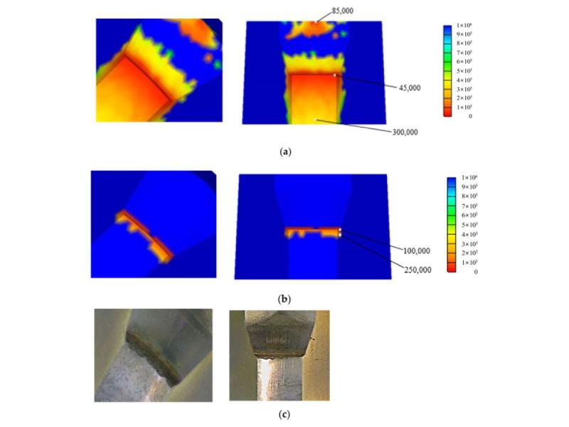
Among the cases investigated was a multi-stage cold forming process for an automotive nut made of S25C. The tool system contained prestressed WC-Co20% inserts and stress rings. The loading generated by the forming process was determined using an implicit finite element simulation and subsequently used for structural analysis and fatigue life evaluation of the tool.
For one critical tool insert, the modified Goodman-Haigh evaluation predicted a minimum HCF life of approximately 45,000 cycles, whereas the newly developed fatigue model predicted approximately 100,000 cycles.
Even more important than the numerical value itself was the spatial prediction. With the extended model, the calculated critical life region was concentrated much more strongly in the area where HCF failure was also observed in the real tool. The authors describe the agreement between simulation and experimental findings as qualitatively good.
The example demonstrates that the choice of fatigue model is not merely an academic issue. It can significantly influence both the predicted life and the localization of the truly critical tool region.
Tool, Billet and Forming Process Constitute One Interacting System
A further study published in 2024 by Byun et al. shows that the cause of tool failure does not necessarily lie solely in the tool geometry itself. The authors investigated the automatic multi-stage cold forging of an automotive wheel nut made of S25C.
Geometrical asymmetries created during shearing of the billet caused tilting and wobbling of the workpiece during the forming operation, shifting its center of mass and leading to asymmetric loading. This resulted in local stress concentrations in critical tool regions that were associated with the observed HCF failure.
AFDEX addresses precisely this interaction in its technical documentation: for short billets produced by shearing, such as those used for nuts, the geometry of the sheared surface can already have a significant influence on the local stress distribution in highly critical tool regions. AFDEX demonstrates both the shearing simulation itself and the resulting tool stress distribution.
This example highlights an important advantage of an integrated forming simulation: the cause of insufficient tool life may lie outside the tool region in which failure actually occurs. Billet geometry, material flow, process sequence, friction, tool prestress and elastic tool response can interact and, under unfavorable conditions, reinforce one another in terms of local tool loading.
From Failure Analysis to Tool Life Optimization
An appropriate AFDEX analysis can therefore be used to investigate a variety of factors, including critical tool stresses and their evolution over time, prestress and stress-ring design, tool radii and transition regions, loads generated in individual forming stages, and the influence of billet geometry and process conditions.
The objective is not merely to reproduce a tool failure that has already occurred. Simulation can be used during process and tool development to identify critical regions before tooling is manufactured and to compare different design variants virtually.
MORPHOTEC offers both forming simulation services using AFDEX and the distribution of the AFDEX software. Companies can initially have specific process or tooling problems investigated by MORPHOTEC, or they can use AFDEX for in-house simulation after appropriate training. MORPHOTEC supports customers in getting started with and applying the software across a broad range of metal forming processes - from cold and hot forming to extrusion, drawing and rolling, as well as selected sheet metal forming applications.
AFDEX is therefore suitable both for companies seeking to investigate a specific problem involving insufficient tool life and for manufacturers wishing to integrate simulation-based process and tool development permanently into their own engineering environment.
References
Joun, M. S.; Ji, S. M.; Chung, W. J.; Cho, G. S.; Lee, K. H. (2022):
A New General Fatigue Limit Diagram and Its Application of Predicting Die Fatigue Life during Cold Forging.
Materials, 15(7), 2351. DOI: 10.3390/ma15072351.
Byun, J. B.; Abd Hamid, N.; Cho, G. S.; Chung, W. J.; Kang, S. M.; Lee, K. H.; Joun, M. S. (2024):
Effect of shearing on production stability and die life in automatic multi-stage cold forging of an automobile wheel nut.
The International Journal of Advanced Manufacturing Technology, 131, 329-341. DOI: 10.1007/s00170-024-13017-9.